Here’s our essential turbo tuning guide to everything you need to know about turbocharger components for tuned cars…
Turbocharging is the easiest way to get more power from an engine. But there’s a lot more to it, than simply bolting on a big turbo and hoping for the best.
How does a turbo work?
A turbocharger forces air under pressure into the engine, rather than letting it rely on its own breathing. This is why they have the potential to massively increase power output. The air is forced into the engine by the compressor (wheel, which is basically a fan that spins at speeds exceeding 100,000rpm) and sometimes squeezing the air to pressures many times higher than the earth’s atmosphere.
The compressor is powered by exhaust gas spinning a turbine wheel, which is connected via shaft to the compressor. The basic turbo principle is very simple. But, to make it work effectively takes a lot more work, and that’s why, despite being over 100 years old, turbocharger technology is constantly still evolving.
A brief history of turbos
The turbo was invented over 100 years ago, in 1905 to be exact. Early production turbos were used almost solely on diesel engines, mostly powering ships, with the first one on a wheeled vehicle in 1938. In the ’30s and ’40s American company General Electric developed and successfully used turbos on petrol-powered aircraft engines, and they saw widespread use on WW2 fighters and bombers.
The first ever turbocharged race car appeared in the 1952 Indy 500, using a diesel engine. At around the same time the first production road vehicles, which were diesel trucks, were becoming available equipped with turbocharged engines.
Turbocharging soon took off and within 10-years it became normal to see turbocharged race cars, by the ’70s some turbocharged race cars were topping 1,000bhp, and turbocharged road cars were becoming commonplace.
Turbocharger components
While turbos only have a few basic components, there’s an almost infinite variety of them. So getting them to work effectively can be very complex. Here, we explains the parts in detail and how they change the turbocharger’s characteristics.
Compressor wheel
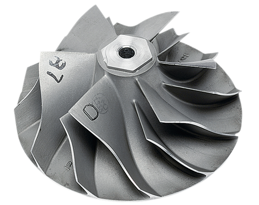
This is the component that sits inside the compressor housing. Its job is to pressurise and force the air into your engine. The compressor wheel is stepped, which effectively gives it two sections of fan blades, named the inducer and exducer. Although not solely responsible for creating bhp, their size gives a good indication of the power potential of the compressor.
The front of the compressor wheel is the ‘Inducer’. A larger inducer diameter generally means a bigger power capability. The rear section of the compressor wheel is the ‘Exducer’. And a large exducer usually means it’s more efficient at high boost pressures.
The word ‘Trim’ when talking about compressors relates to the relationship between the inducer and exducer diameters. While most modern turbos come with an appropriate trim, on performance engines you generally want as high a trim number there is. This means a very large exducer in comparison to the inducer. The number of blades and their shape also effects compressor performance. Developments in this area are making compressors more efficient all the time, so a modern turbo compressor with a 70mm inducer may well be better than an older style turbo with a 70mm compressor inducer.
The latest buzz word for high performance compressors is ‘Billet’. This refers to a compressor wheel that’s machined from a solid billet of aluminium rather than cast in a mould. This means the wheel can be fabricated in a more intricate shape plus more metal can be removed, making a more efficient and higher flowing compressor for its size. Finally, although it is mostly effected by the turbine side, compressor size and weight has some impact on turbo spoolup performance. A lighter, smaller compressor generally gets up to speed faster than a larger one.
Compressor housing
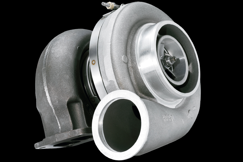
This is the most noticeable part of the outside of a turbo– the ‘snail-shaped’ item the compressor wheel sits inside. It’s a sealed unit with an inlet in the centre and an outlet on the other end of the ‘snail’ spiral. The size of the housing itself, as well as the inlet and outlet ports, varies massively depending on the size of the compressor.
On the whole, larger compressor wheels sit in larger housings. So in its most basic form you can sometimes – very roughly – estimate a turbo’s potential by compressor housing size.
The main variables with compressor housings are the inlets, most significantly, ported shroud or map width enhancement (MWE) inlets. These have special slots cut into them which enable very large compressors to be used on small engines. This means a reduced chance of turbo-damaging compressor surge. It’s also said to potentially increase compressor flow at the limits of its performance.
The final difference to the inlet is that some are bell mouthed or have a trumpet on the inlet. Again, this is a minor thing that can increase compressor efficiency a little. You may have seen a race car turbo fitted with an inlet restrictor. This sits on the front of the compressor housing to limit the amount of air that can enter the turbo, thus limiting power output and also increasing lag. Just what you don’t want on a road car.
Wastegate
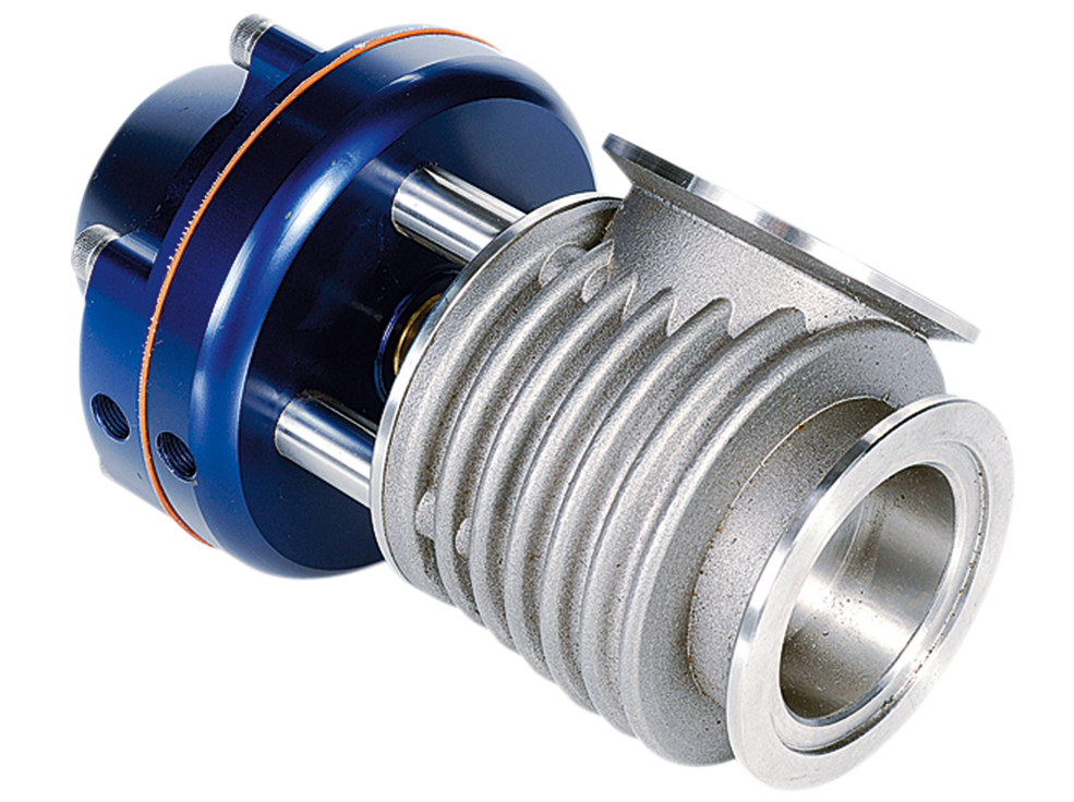
Unless a turbo is either so big it can’t hit full boost before the rev limiter, so small it cant produce much pressure, or has its airflow highly restricted, (in which case you have other serious issues to solve), it needs a way for the exhaust gas to bypass the turbine housing to stop the turbo overboosting. Most smaller turbos have internal wastegates, which are basically flapper valves built into the exhaust housing and controlled by a boost pressure operated actuator.
These make the wastegate setup compact and simple, but due to size limitations they can suffer with boost creep (the condition where not enough exhaust gas can be bypassed, leading to higher boost than required). Most highly tuned and race applications use external wastegates. Although these increase cost and complexity, they can generally bypass far more exhaust gas than an internal wastegate. They can also be mounted elsewhere on the exhaust manifold which can help packaging of the system.
Wastegate postioning
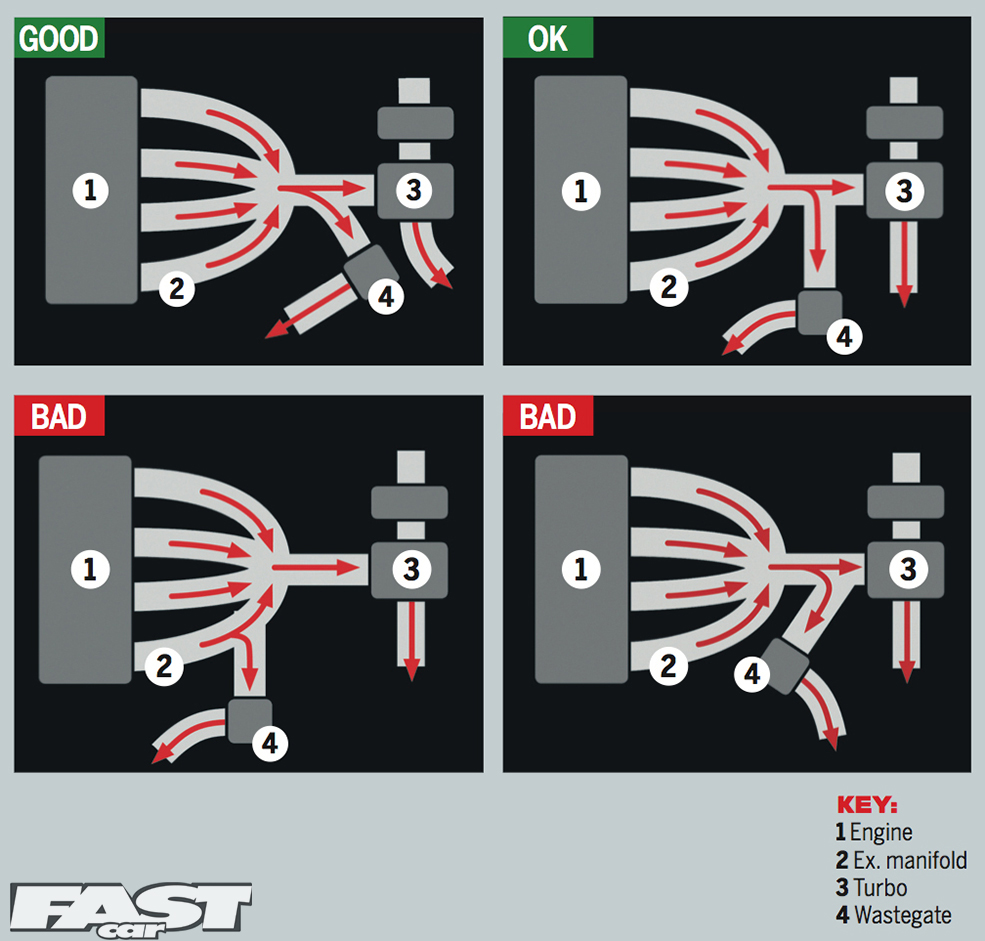
The wastegate needs to be mounted on the exhaust manifold before the turbocharger. But the better the positioning of it, the better it will flow for any given wastegate size. The most important thing is that the wastegate should be able to vent gas from all cylinders. This means it needs to, ideally, be mounted on the collector, just before the turbo. Not all wastegates are like this though, often out of necessity.
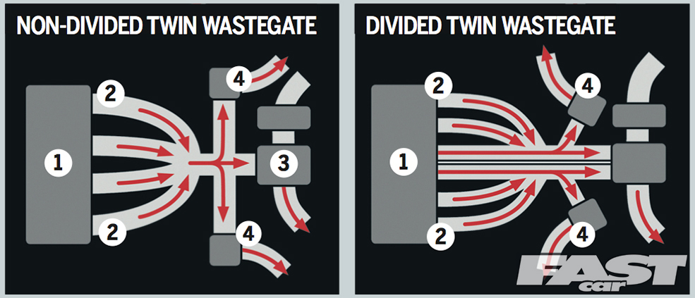
But this significantly reduces flow and can lead to poor boost control and other issues. Secondly, the flow to the wastegate should be smooth (less than 45deg to the direction of the exhaust flow is ideal). But if this is not possible, it should be no more than 90deg if you wish to have any boost control at all. The same principles apply in twin wastegate setups, as shown below.
Twin wastegates
Sometimes, even on standard vehicles there may be two wastegates per turbo. This can be because you can’t fit a single wastegate that’s big enough to bypass enough exhaust gas, due to space considerations.
Or simply because you are running an enormous turbo at low boost. The other reason may be that you want to run a fully divided exhaust manifold setup and you want to have a totally divided wastegate design.
Turbine wheel
The turbine wheel is of a similar design to the compressor wheel. It is spun by the exhaust gasses, and its job is to power the compressor. Just like the compressor, it is stepped and therefore has an inducer and exducer (although on a turbine wheel the overall wheel diameter is the only size worth concerning yourself with). Turbine wheel size defines the amount of flow through the exhaust, and while a larger turbine wheel means slower spooling, more exhaust flow means higher power. To make power air needs to get out of the engine as well as in! In general a larger engine, or one needing to make power at higher rpm needs a bigger turbine wheel than one with a lower capacity or lower rpm limit.
Just as with the compressor side, weight, number of blades, and shape all play a part in turbine wheel performance. But these are things you rarely have the option to adjust with an off- the-shelf turbo.
Turbine wheels can be made of various materials. Most are steel, but many high performance turbos have inconel to withstand extreme heat, and ceramic turbine wheels to improve spoolup. Unfortunately, production ceramic turbines are weak and cannot take high boost pressures, so these are generally replaced with steel ones on tuned cars. Conversely, some urbo race engines from WRC cars and suchlike have incredibly strong, but very expensive ceramic turbines.
Turbine housing
This is the main component your average tuned car fan should be concerned with! Almost every aftermarket turbo available comes with at least three turbine housing option when you buy it.
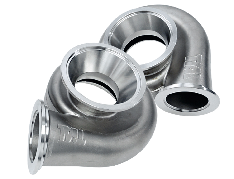
The turbine housing (often called the exhaust housing), covers the turbine wheel and is mounted between the exhaust manifold and the exhaust system. It’s shaped in a similar spiral snail configuration to the compressor, but it works in the opposite way – entering via the outer edge and exiting through the centre.
Varying the turbine housing size can have a dramatic effect on how much power a particular size turbo gives and how fast it spools up. A larger housing will be capable of more power but at the expense of response. This is why there’s usually a choice when you buy a turbo, allowing you to tailor it for your individual requirements.
Just like estimating performance from compressor housing size, you can generally make an estimate about power capability and spoolup by the size of a turbine housing. If it’s as large or larger than the compressor housing, you can be assured it will spool very slowly for the power it has. This would only be suitable on a very large capacity engine.
Another thing to bare in mind is whether to go for divided or twin scroll housings. These, along with a suitable divided exhaust manifold, have the potential to improve spoolup times of the turbo due to feeding the turbine wheel with distinct punches of exhaust gas, rather than one big wave of gas. This can be more effective on some engine configurations than others, but designed well it is certainly beneficial.
The turbine housing also accounts for the main fitment issue of a turbo. This is due to the inlet flange dimensions. There are various sizes, with standard vehicles having all manor of odd variations, but the most common turbo flanges are rectangular ones called T2, T3, T4, and T6, which grow in size accordingly.
These inlet dimensions mean that not only do you need the correct flange on the exhaust manifold to fit them, but the larger the inlet flange is, the higher the exhaust flow can be. It’s worth noting that otherwise identical turbos often produce more power with a larger turbine flange if there is the option available. But your main consideration should be whether it’s the correct flange for your manifold.
The final area to consider, is variable geometry turbine housings. These have a series of veins inside the housing controlled by an actuator that redirect the exhaust gas. This effectively act like a smaller turbine housing at low boost, and a larger one at high boost, giving quick spool up and high peak power, the best
of both worlds. However, they can be complex in their operation, bulky for their power output, and currently are not suited to the high exhaust temps of tuned petrol engines. But they will play a big part in the future of turbos.
Turbo core
This is what joins the compressor and turbine housings together. It also houses the turbo shaft and lubricating oil. Water cooling is used on many turbo cores, but this is mostly to reduce damage when a turbo engine is turned off immediately from a hard run.
The bearings, which support the shaft, are of two types. Either journal bearing or ball bearing. The vast majority of turbos are journal bearing, and work in the same manor as engine bearings. The core and bearings are separated from each other via a think layer of pressurised oil. Ball bearing turbos, on the other hand, have the shaft supported on – you guessed it – ball bearings! These give a slight improvement in spool up and response over an otherwise identical turbo running journal bearings. It’s not all good though. Ball bearing turbos generally cost much more to buy, and when the bearings fail the damage is often catastrophic.
Turbo shaft
This component joins the two all-important wheels of the turbo to each other and enables the compressor to be powered by the turbine. The size and weight of the shaft will change its strength and how quickly the turbo spools up and responds.
The turbine wheel is generally welded to the shaft and the compressor wheel is screwed on with a nut holding it in place. On many performance applications, the compressor housing thread is left-handed. This means that to undo the nut you have to turn it the opposite way to how you’d expect. This eliminates the possibility of the natural forces exerted on the wheel and shaft, undoing the nut over time, which would of course destroy the turbo.
Words Stav Photos Various

